Take a Look at This Fascinating Teardown of the New Canon 70-300mm f/4-5.6 IS II Zoom Lens
(Editor’s Note: This piece is by Roger Cicala, the founder of LensRentals.com. Visit LensRentals.com to rent high quality cameras and lenses.)
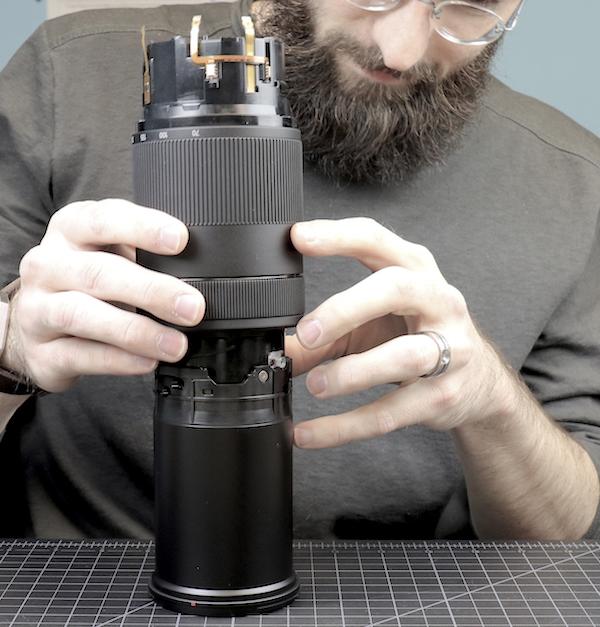
As with most new lenses, a Canon 70-300mm f/4-5.6 IS II made its way back to the repair department for an initial teardown. I know there’s some randomness as to what we tear down, but we have some reasons for doing these. Sometimes, like with this new Canon, it’s simply because we know LensRentals is going to stock a lot of them and we need to take a look inside to see what is likely to break and what parts we may want to order. And other times, like with this new Canon, it’s because there’s some new technology inside we want to take a look at.
And, of course, almost all the time these days, there’s some aphasic marketing terminology that leaves Aaron and I looking at each other wondering “what are they trying to say that is.” This time it was “NANO USM technology.” Did that mean there were little nanobots in there focusing the motors? Or that the focus group only had to move nanometers? The problem seemed to have been compounded because some retail and review sites were claiming it had a stepper motor, a ring USM, or both. That’s what happens, marketing department, when you make up words: nobody understands without explaining what you mean.
Looking inside seemed a good way to clarify that. Though Canon did tell what they meant a little bit, nobody read it. The NANO USM focusing motor made its debut in the Canon 18-135mm f/3.5-5.6 IS NANO USM lens last year, but not many people talked about it. The NANO USM motor is a different focusing system for Canon, although manufacturers have used similar linear piezo systems.
And, as always, we wanted to see what engineering goodness Canon had inside that polycarbonate lens shell. We’re geeks. Sweet design pushes our buttons, and Canon lenses have had a lot of sweet engineering lately. Even though this is a consumer price range lens, the new digital focusing meter was cool, and we wanted to see if some of the impressive engineering Canon had put in their new L series lenses was drifting down to the consumer grade models.
So let’s tear up, I mean let’s carefully dissect, the new Canon 70-300mm f/4-5.6 IS II But first, let’s take a quick look at that nice digital readout. I can’t say it’s all that useful, but the depth-of-field-by-aperture display is a nice touch.

Getting to what we like to do, the bayonet mount and rear light baffle come off in the usual Canon fashion; remove the bayonet mounting screws and pop out the baffle.
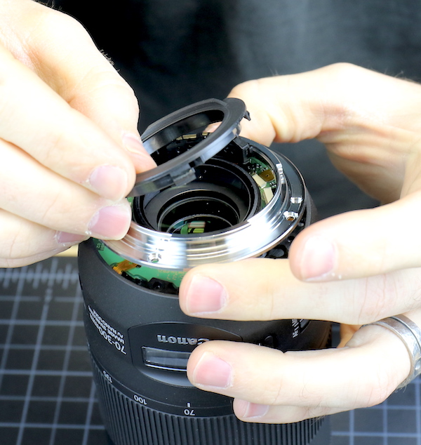
The PCB has quite a few flex connectors, all neatly laid out and with (thank you, Canon) nice reinforced holes in most of the flexes. This makes it a lot less stressful to remove and insert them in their connections.

Disconnect some of those flexes, and the rear barrel comes off quite quickly. The display LCD is self-contained within this barrel, connected only by a flex going to the PCB. I suspect if the screen is damaged they’ll only replace the rear barrel assembly, but that shouldn’t be an expensive part.
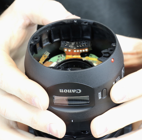
And after disconnecting the remaining flexes and removing two screws, the PCB comes off.

Now we can get a look at the inner rear barrel and the rear element. You can see the hefty mounting screw threads. If you notice the flex at the bottom of the picture, the round yellow dot is the actual electronic button that’s pushed when you push the mode button on the lens barrel (see image above).
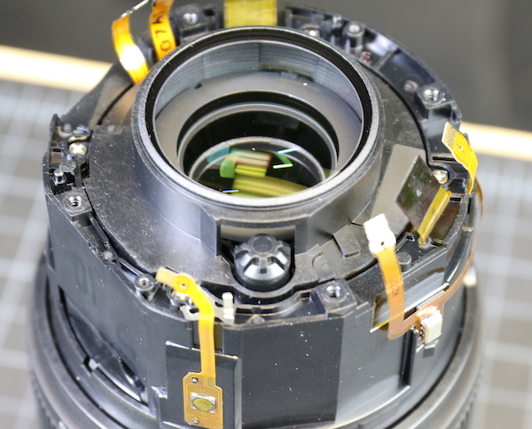
We love working on most of the newer Canon lenses because of the modular construction and the Canon 70-300mm f/5-5.6 IS II is no different. The entire outer barrel with focus and zoom rings, as well as most of the electronics, comes off as a single piece.
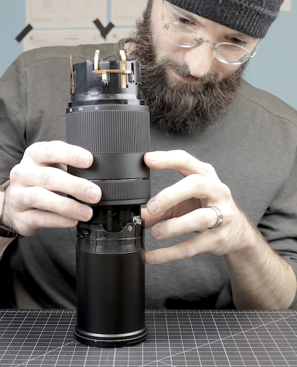
In this rather poor picture, you can see the mount end of the inner barrel. The large brass screws hold the outer zoom barrel to sliding cams on the inner barrel.

The rear group is a fixed, non-centering group that comes off by removing three screws.

Looking at the inner assembly, we saw that there are optical-adjusting eccentric collars (two are pointed at by red lines) on several different elements. Most consumer-priced zooms have one or two adjustable elements at most.
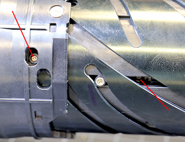
We like taking out some of the screw/collar assemblies that hold the lens elements in place while they slide up and down the helicoid grooves. These do get wear and tear, and we like seeing more robust ones. We weren’t disappointed here; they were metal with nylon bearings. This is the kind of thing we usually see in more expensive lenses.

At the mounting end of the lens, we could see the focusing assembly appeared to be a single modular unit. After removing a few of the screws and collars that hold it in the helicoid, and unhooking some very well stuck down flexes, we were able to slide the entire assembly out.
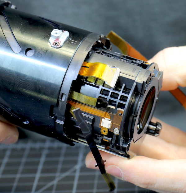
The focusing assembly is pretty self-contained, with a whole lot of stuff in a subtle area. The silver area at the bottom is the actual motor assembly. Another pleasant surprise was there were two more adjusting collars for one of the focusing elements (green lines). When two adjustments are close together like this, usually one is for centering, the other for adjusting tilt. You can see the eccentrics of them a bit better in the next picture.

We really would have liked to stop at this point. We assume that this AF assembly is probably replaced as a unit when anything goes wrong, and it’s probably not meant for disassembly. But just looking at the motor from the outside didn’t show us what we wanted to see and, well, there were screws.

There is also a focus position sensor inside of the barrel we just removed.

While we debated whether the screws just had to be unscrewed, we played around with the AF assembly a bit. You can’t tell from the image above, but the smaller black plastic and aluminum assembly slide linearly (hence linear focusing motor) within the larger aluminum rectangular cage with the writing on it. The image below shows us sliding the carriage from a side view.
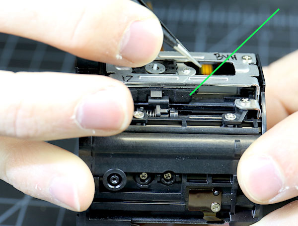
You can see the carriage (green arrow) is relatively thick and the aluminum cage stands up quite a bit from the assembly, which wasn’t apparent in the image above. Also, notice there’s a counter spring to push the carriage back; you can see it on the tip of Aaron’s finger. There’s nothing magnetic in here and certainly no ring motor. It’s clearly a sliding linear piezo type USM.
So we’d seen what we’d come to see. And Canon has published a picture of what the NANO USM motor looks like. We know it’s in there, so there’s no reason to dig any deeper.  Sure, there were more screws. It seemed unnatural to leave them in place. On the other hand, we’d come this far without breaking anything. Logic and reason said leave well enough alone and put the lens back together. So, we started by taking the front ring off.

This was a bit of a dead end, the only thing that taking off the front ring showed us was the bar the focusing group slides up and down on. But it is a nice, thick bar placed into very solid caps at each end, so that’s good.

We put that back where we found it and then started in on the screws holding the motor assembly in place.
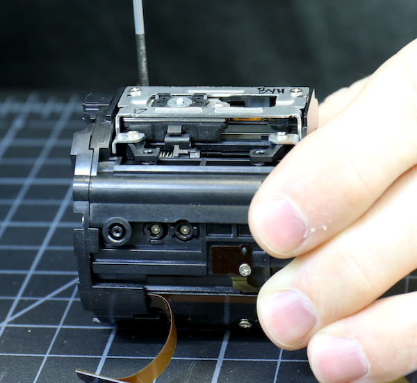
A bit to our surprise, the motor assembly came off as a self-contained unit. It seems logical in retrospect, but at the time we were a bit leery that we’d be breaking a glued-on connection to the focusing elements, which was happily not the case. No glue here, everything snaps into place. I was a little nervous and let this photo be underexposed, but you can see the connection from the focusing element to the motor right above the spring in the image below.

With the motor off, you can see the aluminum case is screwed down onto the plastic base of the motor. You can also see some flexes leaving the motor on the back side, and a couple of grooves on the top of the aluminum that we thought must have some purpose, although we didn’t know what.

We removed the cover case fairly carefully and were glad we did.

You can sort of see two tiny white ball bearings (green arrows) that let the motor assembly slide up and down within the cage (there is a third one on the other side). The grooves we noted above are the tracks for them. If those had fallen out chances were about none that we’d have found them again.
The actual motor is on the bottom side of that assembly, looking just like what Canon showed us above. And yes, even the IS unit on my lens didn’t quite overcome my long-exposure tremor at the thought of trying to find those tiny white ball bearings on our floor.

So What Did We Learn Today?
Well, we already knew Canon was great at optomechanical engineering, and the Canon 70-300mmf/4-5.6 IS II is no exception. And unlike some of their cameras, they don’t seem to have a problem putting all the right features in their consumer grade models. We were impressed by the numerous elements that could be optically adjusted, by the metal collars and rollers, pleasantly modular and robust construction, and the efficient layout.
The new motor is tiny. By claim, it is both fast and accurate, and it appears it will be replacing the STM type motors for use in a lot of lenses. These motors are not incredibly powerful, so they’ll move small groups. Lenses that focus using larger groups will, I imagine, continue to use ring type USM motors. But I saw nothing about the motor that made me think "this is going to fail." It’s a real USM with no gear train and by our examination, no glued together pieces that might separate.
- Log in or register to post comments


